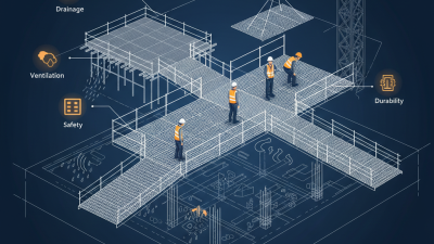
Grating Support is the framework and fixing arrangement that holds open-grid panels in place while people, equipment, or materials pass over them. It may include steel or concrete beams, bearing surfaces, support bars, and clips or other approved fasteners. The exact arrangement depends on the panel type, span, expected loading, and site conditions. A small detail matters: the grating needs enough bearing at each support, not just a fastener at the edge.
In practice, the support members carry loads from the grating into the larger structure. Proper spacing helps limit excessive deflection and movement, while secure connections reduce the risk of panels shifting during use. For example, an installer may check that a panel sits flat on its supports and that clips match the grating profile. A detail is easy to miss. Coatings, drainage, corrosion exposure, and access for inspection can also affect the choice of materials and fixing method. These points should be checked against project drawings, manufacturer guidance, and applicable engineering specifications. It sounds simple, but the phrase “grating support” can refer to several different parts of an assembly, so clear terminology is useful. This guide explains the common support components, how loads travel through them, and what to consider when selecting or inspecting a system. It does not replace project-specific design review; span and load requirements should be verified by a qualified professional.
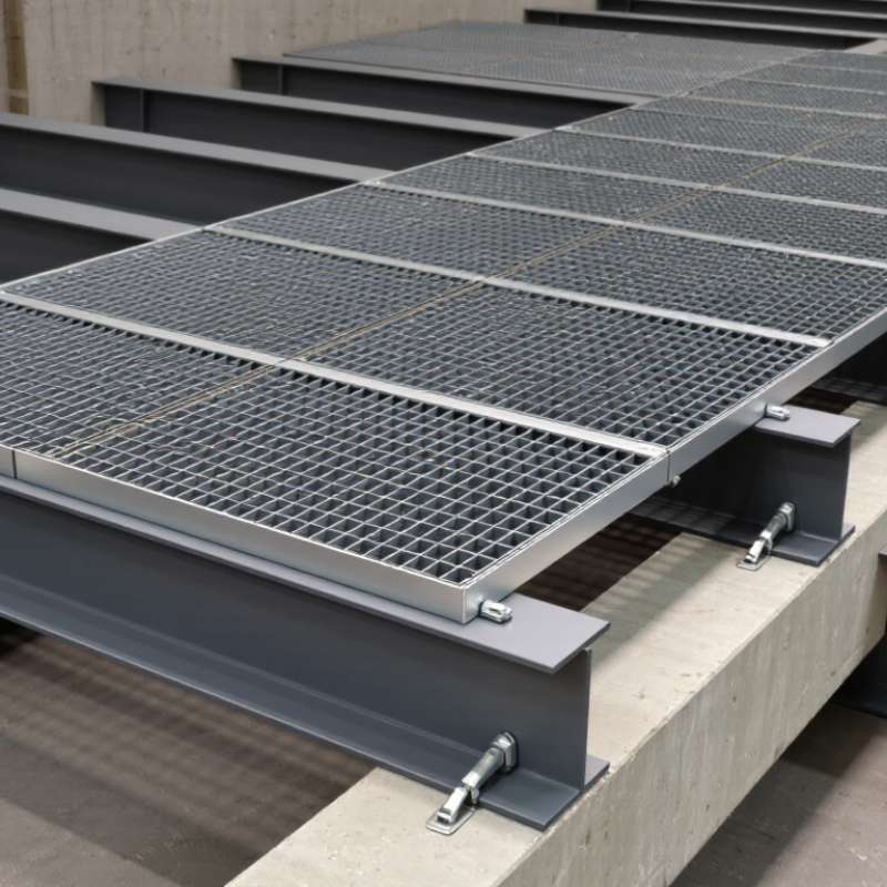
Grating support is the load path beneath an open metal floor. Bearing bars run in the main span direction and carry most of the vertical load. Their depth, thickness, spacing, and unsupported span affect how much the panel deflects underfoot. Crossbars connect the bearing bars, maintain their spacing, and help distribute local loads. They do not replace properly designed supports beneath the panel.
Supporting steel—such as beams or support angles—carries the panel’s load into the larger structure. A grating panel may look rigid, but a loose edge or oversized span can cause movement, noise, or unsafe deflection.
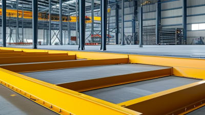
Grating support is the structure beneath a panel that receives its load and carries it onward. A person, cart, or stored item presses on the grating. The bearing bars bend slightly and transfer that force to the beams they rest on. Short spans usually feel firmer underfoot. Long spans may flex more, even when the panel remains within its design limits.
The beams then pass the load to larger supporting members, such as girders or columns. Columns carry it down to the base and foundation. That path depends on sound contact: bearing bars should sit on their supports with adequate end bearing, while properly selected clips or welds help keep panels from shifting or lifting. The fasteners do not automatically replace the beam’s supporting role. Small details matter. A gap, loose clip, or uneven seat can cause rattling and movement. It is easy to focus only on the grating’s stated load capacity, but support spacing, panel direction, concentrated loads, and beam strength also affect performance. I would check those together rather than assume a panel rating tells the whole story. The final layout should be verified against the actual loads and site conditions by a qualified structural professional.
| What Is Grating Support and How Does It Work? - How Loads Pass from Grating Panels to Beams and Columns | ||||
|---|---|---|---|---|
| Stage | Component | Role in the Load Path | How the Load Is Transferred | Typical Checks |
| 1 | Load on the grating | A person, stored item, or equipment applies a load to the walking surface. | The load acts on one or more grating bars, depending on its size, position, and the panel layout. | Identify the load type, location, and applicable project design requirements. |
| 2 | Bearing bars | The primary load-carrying bars span between supporting members. | Bearing bars bend between supports and carry much of the load across the span. Their orientation should suit the intended support direction. | Confirm bearing-bar direction, span, panel capacity, and deflection limits. |
| 3 | Cross bars | Cross bars connect and stabilize the bearing bars and help distribute local loads across the panel. | They transfer load between bearing bars and help the panel act as a connected unit; they do not replace the primary bearing supports. | Check panel construction, connection integrity, and the manufacturer’s published capacity data. |
| 4 | Panel edges and bearing seats | The panel ends or edges rest on supporting steel, concrete, or another designed seat. | Support reactions pass from the bearing bars into the supporting members through the panel’s bearing contact. | Verify adequate bearing, alignment, edge clearance, and that the panel is seated as detailed. |
| 5 | Panel-to-support restraints | Clips, bolts, or other specified fasteners help keep panels in position. | Restraints resist movement or uplift where required. They are distinct from the bearing surface that carries gravity load. | Use the specified restraint type and spacing; check for secure installation and access for inspection. |
| 6 | Beams or supporting members | Beams receive reactions from the grating panels and carry them toward the main structure. | The beam distributes the reactions through its span to its supports, such as columns, walls, or other beams. | Check beam strength, deflection, connections, and the combined effects of other supported loads. |
| 7 | Columns and foundations | Columns and their foundations complete the vertical load path to the ground. | Beam reactions pass through structural connections into columns and then into the foundation and supporting soil or structure. | Confirm the complete load path, including column capacity, connection design, and foundation adequacy. |
| Design note: This table describes a typical gravity-load path. Actual capacities, spans, support details, and fastening requirements depend on the grating specification, loading, applicable codes, and project-specific structural design. | ||||
How Span and Deflection Guide Support Design, Including the L/200 Criterion
Grating support is the frame or set of bearing members beneath a panel. It transfers foot traffic, equipment loads, and other forces into the structure. The clear span is the unsupported distance between bearing points. A longer span usually means greater bending and deflection, so support spacing matters. Measure the actual clear distance, not just the panel’s overall length.
Deflection describes how far the grating bends under load. Some specifications use L/200 as a serviceability limit: divide the span by 200 to find the permitted movement. For a 1,200 mm span, that equals 6 mm. Treat this as a design criterion, not a universal rule; project requirements and product data may set different limits. Support strength, grating direction, connection details, and concentrated loads also matter. A neat calculation can still miss a loose bearing or an unexpected load.
Tips: Check the manufacturer’s load tables and the governing project specification. Confirm each panel bears securely on its supports, and inspect the finished installation for rocking or uneven contact. Small gaps are easy to overlook.
In 19-W-4 bar grating, “19-W-4” describes two important spacings: bearing bars sit 1-3/16 inches apart, and crossbars are spaced 4 inches apart. The bearing bars are the primary load-carrying members. They should run between the supporting beams, transferring deck loads into the structure below. Orientation matters. Rotating a panel can change its clear span and load performance.
The crossbars connect and hold the bearing bars at consistent intervals. They help the panel act as a stable unit, but they do not replace proper structural support. That distinction is easy to miss. A worker may see a rigid panel and assume it can span farther than intended. The spacing alone is not a capacity rating.
For installation planning, check the support layout, bearing-bar direction, panel dimensions, and applicable load tables. Confirm that each panel has adequate bearing at its supports and that openings or cutouts do not interrupt critical bars. Small details matter. A narrow gap or shifted support can affect fit and performance. When drawings leave the span or loading unclear, get the design checked by a qualified professional before installation. The 19-W-4 designation identifies spacing, not a universal safe load.
What Is Grating Support and How Does It Work?
Grating support transfers people, tools, and equipment loads through bearing bars into structural beams. The bars must span in the intended direction and rest securely on suitable supports. NAAMM MBG 531 provides technical guidance for metal bar grating selection, loading, and installation. Use project-specific calculations to confirm span, load capacity, and deflection. A grate that feels firm underfoot may still need careful checking.
OSHA 1910.29 addresses fall-protection systems, including guardrails near exposed edges and openings. It does not calculate grating spans or replace structural design. Instead, it informs how workers are protected around elevated walking surfaces. Support details matter here: gaps, loose panels, or poorly secured edges can create hazards. Field conditions can differ from drawings, so inspect the installed work, not just the plans.
Tips: Confirm bearing-bar direction and support contact before installation. Secure panels against movement, and check openings and edge protection during inspections. If the load or site conditions are unclear, pause and obtain qualified engineering review.