Leave Your Message

China Best Bottom Dead Center Detector Manufacturer?

Choosing the China best Bottom Dead Center Detector manufacturer requires more than comparing prices or polished catalog images. It demands practical verification. A reliable supplier should understand crankshaft geometry, encoder resolution, sensor mounting, vibration, temperature drift, and timing errors. These details decide whether a detector performs accurately beside a production press, engine test bench, or automated assembly line.

Professor John B. Heywood, a respected internal-combustion-engine researcher, has repeatedly stressed the importance of precise engine measurement. His well-known statement, “Engine measurements are only as good as the methods used to obtain them,” captures an essential lesson for this market. A Bottom Dead Center Detector must produce stable, repeatable signals under real operating conditions. Ask for calibration records, repeatability data, response-time tests, and examples from comparable equipment. Request photographs of the installation area. Small mounting differences can create large timing deviations.

Experience matters.

A capable Chinese manufacturer should explain its sensing method clearly, whether it uses optical, magnetic, inductive, or encoder-based detection. It should also describe signal output, protection rating, software compatibility, and after-sales support. Certifications are useful, but they do not replace test evidence. Some suppliers may provide excellent hardware yet weak documentation. Others may offer impressive specifications without proving field performance. That is where careful evaluation becomes necessary.

The word “best” is never universal. The right manufacturer is the one that matches your machine, accuracy target, environment, and service expectations. A thoughtful comparison reveals that answer.
China Best Bottom Dead Center Detector Manufacturer?

What Is a Bottom Dead Center Detector?

What Is a Bottom Dead Center Detector?

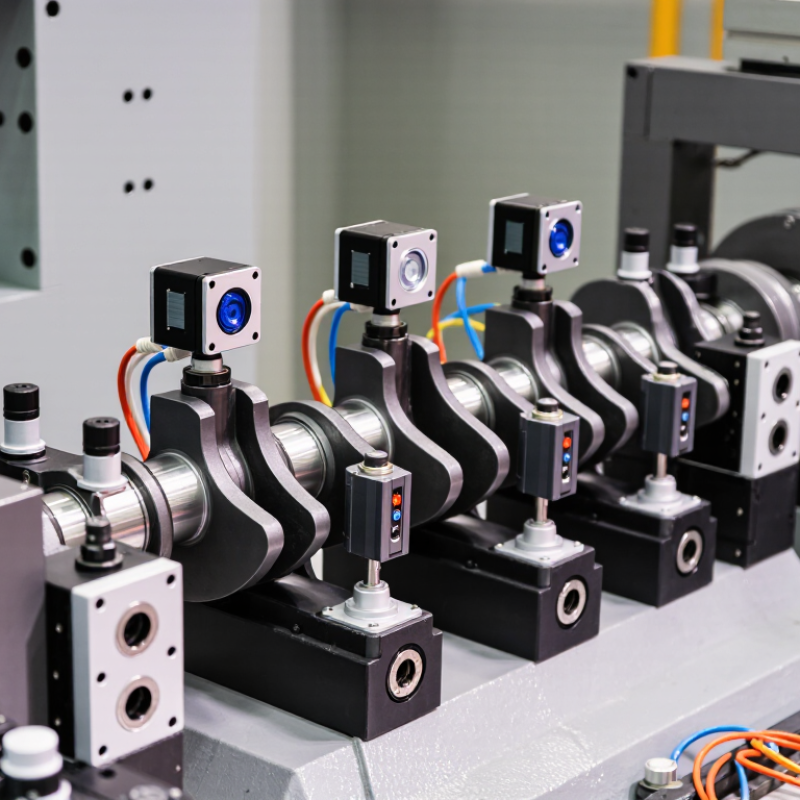
A bottom dead center detector identifies when a press ram reaches its lowest programmed position. It commonly uses a rotary encoder, proximity sensor, or linear displacement transducer. The signal confirms ram location before the machine continues its cycle. In practical commissioning, technicians check the sensor beside the crankshaft or slide, then compare its signal with the controller’s position value. A stable reading matters.

The detector supports safer, more repeatable forming operations. It can help identify incomplete strokes, excessive travel, and position drift before defective parts accumulate. The International Federation of Robotics reported 541,302 industrial robots installed worldwide in 2023. As automation expands, reliable position feedback becomes more important around connected presses and transfer systems. However, a bottom dead center detector is not a complete safeguarding device. It should work with guarding, emergency stops, control interlocks, and scheduled inspection.

Selection requires more than checking detection range. Engineers should review repeatability, response time, vibration resistance, ingress protection, electrical compatibility, and tolerance to oil or metal dust. ISO 16092-2 highlights the need to manage mechanical and control-system risks in power presses. That guidance supports a layered approach, not reliance on one sensor. In my experience, alignment is often underestimated. A detector may pass factory testing yet produce unstable readings after installation. Cable routing, loose brackets, and incorrect calibration can quietly reduce reliability. Periodic testing with recorded ram positions exposes these weaknesses. The best supplier also provides traceable test data, installation guidance, and technical support for the actual press configuration.


How Bottom Dead Center Detection Works

How Bottom Dead Center Detection Works

Bottom dead center (BDC) is the lowest position of a moving slide, ram, or piston. A detection system identifies this position by tracking shaft rotation and mechanical movement. In many machines, an encoder measures crank angle, while a proximity sensor confirms a physical reference point. The controller compares both signals during every operating cycle.

The process begins with a calibrated reference mark. As the crank approaches its lowest point, the encoder sends angle data to the control unit. The sensor then verifies the expected position. If the signals disagree, the system can trigger an alarm or stop the cycle. This dual-check method improves practical reliability.

Real machines are not perfectly rigid. Load changes can cause deflection, and heat may slightly shift sensor timing. Backlash can create another small error. A test technician should check several cycles at different speeds and loads. The readings should remain stable, not merely appear correct once. Keep cables shielded and sensors firmly mounted. Small details matter.

A useful system also records position history and fault codes. This helps maintenance teams find drift before it affects production quality. Still, detection accuracy depends on installation, calibration, and mechanical condition. Better hardware cannot fully correct a loose coupling or worn bearing. That point is easy to overlook.

Key Features of China’s Leading Manufacturers

China Best Bottom Dead Center Detector Manufacturer?

China’s leading manufacturers focus on repeatable measurement, not attractive specifications alone. A reliable bottom dead center detector should provide stable position accuracy, fast response, and resistance to oil, vibration, and temperature changes. Magnetic and optical sensing options are common. Magnetic units often suit enclosed engine fixtures, while optical units can offer sharper timing signals in controlled environments.

The 2024 MarketsandMarkets Automotive Sensors Market report identifies growing demand for precise sensing in engine control and testing systems. Its forecast indicates continued expansion through 2029, driven by automation and stricter efficiency requirements. This trend affects detector design. Leading manufacturers now provide adjustable mounting brackets, shielded cables, real-time signal output, and compatibility with PLC or data-acquisition systems. Small details matter. A loose bracket can shift the measured crank angle.

Quality control should include calibration records, repeatability testing, and inspection under simulated vibration. ISO 17025-based calibration practices can improve measurement confidence, although certification alone proves nothing. I would still ask for raw test data. The 2024 World Robotics report also records strong industrial robot adoption in China, supporting more automated engine-testing production lines. However, automation does not remove every error. Sensor alignment, connector wear, and operator setup still deserve practical checks. A strong supplier offers technical drawings, sample testing, responsive support, and traceable inspection results before large-volume production begins.

China Best Bottom Dead Center Detector Manufacturer? - Key Features of China’s Leading Manufacturers

Evaluation Dimension Typical Specification or Capability Why It Matters
Detection Technology Inductive proximity, photoelectric, laser displacement, or linear position sensing Allows the detector to be matched with press speed, tooling structure, and required positioning accuracy.
Positioning Accuracy Approximately ±0.01 mm to ±0.10 mm, depending on sensor type and installation Higher accuracy improves bottom dead center repeatability and reduces die alignment errors.
Repeatability Typically ±0.01 mm to ±0.05 mm for precision positioning applications Stable repeatability helps maintain consistent forming depth and production quality.
Detection Distance Common sensing ranges from 1 mm to 10 mm for proximity devices; longer ranges are available with optical systems The correct range prevents false signals caused by vibration, stroke variation, or target movement.
Response Time Usually below 1 ms to 10 ms for industrial sensing models Fast response supports high-speed presses and timely machine-control feedback.
Electrical Supply Commonly 10–30 V DC, with 24 V DC widely used in industrial control systems Compatibility with standard control cabinets simplifies installation and maintenance.
Output Signal PNP, NPN, relay, pulse, analog voltage, analog current, or fieldbus-dependent output The output must match the PLC, motion controller, safety circuit, or press control system.
Protection Rating IP65 to IP68 is commonly available for dust- and moisture-exposed production areas A suitable enclosure rating improves reliability in environments with oil mist, dust, and coolant.
Operating Temperature Common industrial range: approximately −25°C to +70°C Temperature tolerance helps maintain stable performance near presses and other heat-generating equipment.
Mechanical Construction Threaded cylindrical, compact rectangular, flush-mount, or rail-mounted housing Different housing formats support limited spaces and varied press-tool configurations.
Calibration and Adjustment Teach-in, sensitivity adjustment, zero-point setting, and adjustable switching distance Simple adjustment reduces commissioning time and accommodates tooling changes.
Communication and Integration Discrete I/O for basic systems; analog or industrial network communication for advanced monitoring Integration options support alarms, production records, diagnostics, and predictive maintenance.
Typical Applications Mechanical presses, stamping lines, forming machines, servo presses, and automated die systems The detector confirms the lower stroke position and helps prevent incomplete forming or tooling damage.
Quality and Compliance Documented inspection, traceability, electrical safety testing, and applicable ISO-based quality procedures Quality documentation supports consistent procurement, validation, and long-term service.
Customization Support Custom cable lengths, connectors, mounting brackets, sensing ranges, and output configurations Customization can reduce retrofit work and improve compatibility with existing press equipment.

Note: Specifications shown are typical ranges and capabilities commonly available from established industrial sensor manufacturers in China. Actual performance depends on the sensing technology, model, installation conditions, and control-system configuration.

How to Evaluate Detector Quality and Accuracy

Choosing the China best bottom dead center detector manufacturer requires more than comparing prices. Quality begins with traceable measurement. ISO 230-2 recommends evaluating positioning accuracy and repeatability under defined conditions. A detector should therefore be tested at the actual machine, not only on a laboratory bench.

Accuracy claims need clear evidence. NIST Technical Note 1297 states that measurement uncertainty should include relevant error sources and report expanded uncertainty, commonly with coverage factor k=2. Ask for calibration records, uncertainty budgets, sampling intervals, and test temperature. For example, a detector claiming ±0.01 mm should explain whether this includes sensor drift, vibration, mounting error, and signal delay. Without those details, the number is incomplete.

Repeatability matters during production. Run at least 30 cycles, record missed detections, and compare cold-start results with readings after several hours. Check response time with a high-speed data logger. A reliable detector should maintain stable signals when oil mist, dust, or moderate vibration appears. Its housing, cable protection, and connector retention also deserve inspection. One weakness remains easy to overlook: impressive accuracy can collapse after installation. A carefully designed fixture may matter more than a smaller laboratory error. That is why supplier audits should include raw test data, failed samples, maintenance intervals, and an independent recheck.

How to Evaluate Bottom Dead Center Detector Quality and Accuracy

This chart shows the measured crank-angle deviation from the true Bottom Dead Center position across repeated test cycles. A high-quality detector should maintain low error, strong repeatability, and a stable signal near 0° crank angle.

Applications, Installation, and Maintenance Guidelines

A bottom dead center detector is used in stamping presses, forming machines, and automated production lines. It identifies the ram’s lowest position with repeatable timing. This signal helps control part release, die opening, and cycle confirmation. It can also support equipment protection when the ram stops outside its expected position. Small timing errors matter. A few millimeters can affect forming quality and tool life.

Installation requires a rigid mounting bracket and a clear sensing target. Isolate electrical and mechanical energy before work begins. Position the detector according to the machine drawing, not by visual guesswork. Keep the sensing gap stable through the full stroke. Route cables away from motors, heaters, and moving linkages. Use suitable shielding and secure every cable bend. Connect the output to the control system, then test the signal during a slow manual cycle.

Maintenance should include cleaning oil film, metal dust, and moisture from the sensing face. Check the bracket for looseness during routine inspections. Operators can compare the detected position with the mechanical reference mark. Record unusual delays, unstable signals, and repeated stops. I once assumed a clean sensor was accurate, but the bracket had shifted slightly. That mistake showed the value of checking mounting stiffness, not only sensor cleanliness. Calibration may be needed after die changes, heavy impact, or electrical repairs. Test again at normal operating speed. Keep records. Small records reveal large patterns.